Business

Business
An International Effort to Compare Methane Hydrate Reservoir Simulators
The National Energy Technology Laboratory (NETL) and the U.S. Geological Survey (USGS) are guiding a collaborative, international effort to compare methane hydrate reservoir simulators. The intentions of the effort are: (1) to exchange information regarding gas hydrate dissociation and physical properties enabling improvements in reservoir modeling, (2) to build confidence in all the leading simulators through exchange of ideas and cross-validation of simulator results on common datasets of escalating complexity, and (3) to establish a depository of gas hydrate related experiment/production scenarios with the associated predictions of these established simulators that can be used for comparison purposes.
Simulation of gas hydrate reservoir production involves solution of a complex combination of highly coupled fluid, heat, and mass transport equations combined with the potential for formation and/or disappearance of multiple solid phases in the system. Also, the physical and chemical properties of the geologic media containing gas hydrate are highly dependent on the amount of gas hydrate present in the system at any given time. Gas hydrate modelers have used many different conceptual models and mathematical algorithms to solve these problems; each approach has certain advantages and disadvantages but none is either completely accurate or proven reliable from first principles. Given the wide range of differing approaches taken by the various groups developing simulators, this international code comparison effort is the first attempt to explore and understand the impacts of these modeling assumptions on production scenarios involving gas hydrates.
If you are interested in more information, please contact the study co-coordinator, Dr. Brian Anderson. (Brian.Anderson@mail.wvu.edu or 304-293-2111 x2435)
Researchers Involved in the Study (click on researcher name for email)
An Overview of Selected Simulators
Lawrence Berkeley National Laboratory, with support from NETL, developed the first publicly available model designed exclusively to simulate gas hydrate reservoir behavior and production potential (TOUGH+/HYDRATE). TOUGH+/HYDRATE is the most recent implementation of the TOUGH-Fx/HYDRATE code. In addition, NETL has released a freeware, open-source, earlier version of the code under the name HydrateResSim. This open-source version of the code is available for use as a .zip file. To receive this file please e-mail Isaac.Gamwo@netl.doe.gov, and NETL will provide a limited level of user support for this version of the code, potentially including the development of future updates based on modifications made and/or suggested by users of the code.
In addition to these codes, other groups have developed simulators based on widely differing approaches to gas hydrate simulation. For example, MH-21 Hydrate Reservoir Simulator (MH-21 HYDRES ), developed by the National Institute of Advanced Industrial Science and Technology, Japan Oil Engineering Co., Ltd. and the University of Tokyo has been specifically designed to assess production from gas hydrate deposits. The Pacific Northwest National Laboratory and the Petroleum Engineering Department at the University of Alaska, Fairbanks have modified the multi-phase simulator (STOMP) to allow for the inclusion of gas hydrates (STOMP-HYD ). Also, those investigating Alaska North Slope gas hydrate resource potential as part of a BP Exploration Alaska, Inc. (BPXA) research project in collaboration with the US DOE have extended work begun at the University of Calgary and the University of Alaska-Fairbanks to apply a commercially available simulator (CMG STARS) to model production from characterized gas hydrate-bearing reservoirs.
In addition to these more comprehensive and mature efforts, numerous other groups have developed their own simulators for use on specific examples and/or classes of laboratory through field gas hydrate-related experiments and characterizations.
Case Studies
The suite of problems being considered by the group is currently under development. Given below are a series of links to detailed problem statements, and the results reported by the modeling groups for their various models.
Problem 1
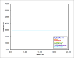
Processes of interest to the simulation of CH4 production from gas hydrates in porous media include multifluid flow and heat transport along with complex phase transitions, including hydrate dissociation and formation. Before executing problems with the additional complexities involved with the gas hydrate phase, a base case problem has been designed to examine the numerical simulation of multifluid flow and heat transport processes with a single phase transition from aqueous saturated to unsaturated conditions for a water-CH4 system outside the stability region for gas hydrate formation. The problem involves a horizontal one-dimensional closed domain (no flow boundary conditions), initialized with gradients in aqueous pressure, gas pressure, and temperature that yield aqueous saturated conditions on half of the domain and aqueous unsaturated conditions on the other half of the domain. The simulation then proceeds to an equilibrium condition in pressure and temperature. The results of numerical simulations of CH4 hydrate formations in geologic media largely depend on the computation of thermodynamic and transport properties. Therefore, a portion of this problem involves reporting property data for selected temperatures and pressures. This problem is a non-gas hydrate case to test basic mass and heat transfer capabilities in the codes. Excellent agreement was observed between the five models, as can be seen from the sample figure below. The detailed problem statement (pdf) as provided by Dr. White (PNNL) and model outputs (an Excel spreadsheet including data from all of the contributors as well as summary graphics) can be found at the following locations:
Problem 1 – Nonisothermal Multifluid Transition to Equilibrium:Problem Description [PDF-392KB]; Model Outputs [Excel - 437KB]
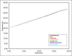
Day 10 Temperatures
Day 10,000 Temperatures
Problem 2
This second problem builds off of Problem 1, but includes hydrate. In it, one half of a 20-m, one-dimensional horizontal domain, discretized using uniformly spaced 1-m grid cells (optionally 0.1-m grid cells) is initialized with aqueous-hydrate conditions; the other half of the domain is initialized with gas-aqueous conditions. As with the Base Case problem, a closed horizontal domain is used to eliminate gravitational body forces and boundary condition effects. The initial conditions are specified to yield complete dissociation of the hydrate, via the thermal capacitance of the domain-half initialized with gas-aqueous conditions. To initialize the aqueous-hydrate half of the domain, temperature, pressure, and hydrate saturation are specified. For reference purposes the hydrate equilibrium pressure, hydration number, and cage occupancies will also be specified for this half of the domain. To initialize the gas-aqueous half of the domain temperature, aqueous pressure and gas pressure are specified. All active phases (i.e., aqueous, gas, and hydrate) are assumed to comprise water and CH4, and capillarity is assumed between the active phases. Hydrate dissociation is assumed to occur using equilibrium kinetics (i.e., infinitely fast dissociation rates). From the specified initial conditions, the simulations proceeds to equilibrium conditions in temperature and pressure, dissociating the hydrate during the transition process and leaving gas-aqueous conditions.
Problem 2 – Closed-Domain Hydrate Dissociation: Problem Description [PDF-1.01MB]; Model Outputs [Excel - 11MB]
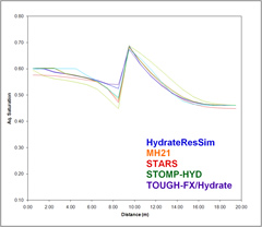
Day 10 Aqueous Saturation
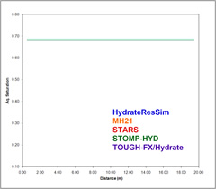
Day 10,000 Aqueous Saturation
Problem 3
The third problem again involves a one-dimension spatial domain. In this test problem, however, a fine gridding of a small domain was used (30 gridblocks, each having a length of 0.05 m, for an overall extent of 1.5m). While Problem 2 explores the behavior of the simulators when hydrate dissociates in the (larger) closed domain of Problem 1, the intent of Problem 3 is to explore fine-scale effects of hydrate dissociation in a non-closed system (ie., gas is produced from the reservoir at the origin). To explore the range of potential behavior, three separate cases were defined: (i) thermal stimulation at the origin (the initial conditions are such that no ice forms during the simulation as a result of dissociation); (ii) depressurization at the origin to a pressure above the quadruple point (again assuring that no ice forms in the domain); and (iii) depressurization at the origin to a pressure below the quadruple point (in which case, there is the potential for the formation of ice). The complete problem description (as provided by G. Moridis, LBNL) can be found at the link below:
Problem 3 – Dissociation in a 1-D open domain: Problem Description [PDF-56KB]
Model Outputs - Problem 3
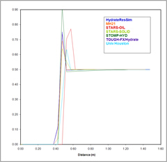
Case 1 - Day 2 Hydrate Saturation
Case 2 - Day 2 Hydrate Saturation
Case 3 - 20 Minutes Hydrate Saturation
Problem 4
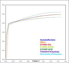
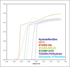
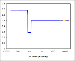
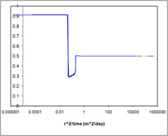
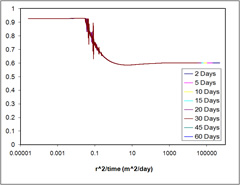
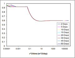
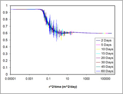
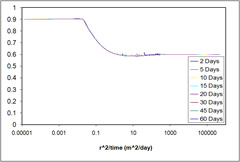
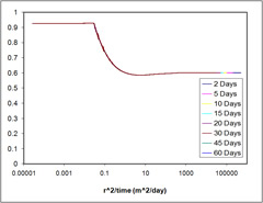
Taking the next step, the fourth problem models hydrate dissociation in a one-dimensional radial domain. The length and height of the domain is 1000 m x 1.0 m with the following discretization: 1000 radial cells with a delta-r of .02 m, followed by 500 cells logarithmically distributed from r = 20 m to r = 1000 m, then 1 cell (the outer boundary) with a delta-r of 1.0e-3 m. The fine discretization utilized in this problem is needed to accurately capture the simulated front during thermal dissociation. As with Problem 3, this problem explores the fine scale effects of hydrate disassociation in a non-closed system. Like the previous problem, Problem 4 also seeks to investigate the range of behavior by simulating two separate cases: (i) thermal stimulation at the origin, and (ii) depressurization at the origin. The complete problem description can be found at the link below:
Problem 4 – Hydrate dissociation in a radial domain: Problem Description [PDF-55KB]
Model Outputs - Problem 4
Problem 4 Case 1
Case 1 - HydResSim Aqueous Saturation
Case 1 - MH21 Aqueous Saturation

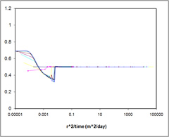
Case 1 - STARS Aqueous Saturation
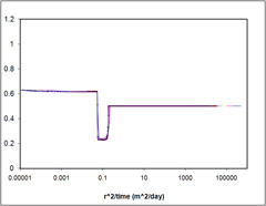
Case 1 - STARS-Mehran Aqueous Saturation
Case 1 - TOUGH-Fx/Hydrate Aqueous Saturation
Case 1 - STOMP Aqueous Saturation
Problem 4 Case 2
Case 2 - HydResSim Aqueous Saturation
Case 2 - MH21 Aqueous Saturation

Case 2 - STARS Aqueous Saturation
Case 2 - STARS-Mehran Aqueous Saturation
Case 2 - TOUGH-Fx/Hydrate Aqueous Saturation
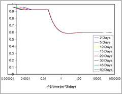
Case 2 - STOMP Aqueous Saturation
Problem 5
The fifth problem models hydrate dissociation in a two-dimensional radial domain. A 10 m hydrate zone in bounded vertically by two 25 m shale zones. The length and height of the domain is 1000 m x 60 m with the four different discretization models: (i) 200 radial cells logarithmically distributed from rw = 0.10795 m to r200 = 1000 m with 30 cells in the z-direction (5 x 5 m, 20 x 0.5 m, 5 x 5 m). (ii) 200 radial cells logarithmically distributed from rw= 0.10795 m to r200 = 1000 m with 11 cells in the z-direction (5 x 5 m, 1 x 10 m, 5 x 5 m). (iii) 50 radial cells logarithmically distributed from rw = 0.10795 m to r50 = 1000 m with 30 cells in the z-direction (5 x 5 m, 20 x 0.5 m, 5 x 5 m). (iiii) 50 radial cells logarithmically distributed from rw = 0.10795 m to r50 = 1000 m with 11 cells in the z-direction (5 x 5 m, 1 x 10 m, 5 x 5 m).Problem 5 also seeks to investigate a range of behavior by simulating two separate cases: (Case A) 80% initial methane hydrate saturation, and ( Case B) 70% initial methane hydrate saturation. The complete problem description can be found at the link below:
Problem 5 – Hydrate dissociation in a radial domain: Problem Description [PDF-128KB]; Discretization Models [Excel - 22.5KB]; Model Outputs [Excel-15.7MB]
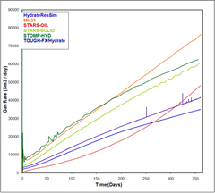
Case A-1 Gas Rate/Time
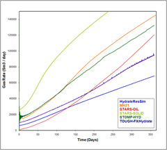
Case B-1 Gas Rate/Time
Problem 6
Problem 6 is based on well test data from a gas hydrate reservoir (Mt Elbert stratigraphic test well) using Schlumberger’s Modular Dynamics Formation Tester (MDT) wire line tool. Four such MDT tests, ranging from six to twelve hours in duration, and including a series of flow, sampling, and shut-in periods of various durations, were conducted. History matches of one multi-stage, 12-h test (the C-2 test) is described as problem 6 by the code comparison participants. Simulations utilized detailed information collected across the reservoir either obtained or determined from geophysical well logs, including thickness (11.3 m, 37 ft.), porosity (35%), hydrate saturation (65%), both mobile and immobile water saturations, intrinsic permeability (1000 mD), pore water salinity (5 ppt), and formation temperature (3.3-3.9°C). Each modeler was given the freedom to determine the approach to conducting these history matches with respect to determination of the numerical grid, approach to finding fitting parameters, etc. The only constraints placed on the efforts were based on the experimental setup (i.e., the location of the tool in the formation, the size of the wellbore, etc), experimentally observed properties of the formation (porosity, initial saturations, temperatures, etc), and the MDT test data
Problem 7
The Majority of the permafrost gas hydrates in the United States are found in the Alaskan region due to the favorable geologic settings. Three different sites were chosen: the Mt. Elbert site at Milne Point, the Prudhoe Bay L-Pad deposit, and a theoretical accumulation of Prudhoe Bay L-Pad site. Mt. Elbert was the site of the BP/US DOE Modular Dynamics Testing in February 2007 and has extensive well log data. The Prudhoe Bay sites are deeper reservoirs. For simplicity in this study, the anisotropy of the reservoirs has been replaced with the average of each of the reservoir parameters obtained from NMR well log data.
Problem 7a is based on the Mt. Elbert site. It is a cold reservoir and hydrate is extremely stable making it difficult to produce gas. The outer radius of the entire grid is 450 m and is 152.5 m deep. A 12.5m hydrate zone is surrounded by two 70m shale zones. It is solved using a radial cylindrical domain with 80 cells logarithmically distributed from r = rw = 0.111m. (rw = well bore radius) to r = 450m in the r direction and 70 cells in the z direction.
Problem 7b originates from Prudhoe Bay L-Pad site. This reservoir consists of two hydrate bearing layers surrounded by three shale zones. A radial grid of outer radius 450m and 240m deep is considered in this problem.
Problem 7c uses the same reservoir as that of Problem 7b. The only difference being that it is deeper and thus warmer than the 7b reservoir.
Problem 7 - Long-term simulations for Mt Elbert and PBU LPad “Like” Deposits: Problem Description [PDF-268KB];
References
Anderson, B. J.; Hancock, S.; Wilson, S.; Collett, T.; Boswell, R.; Hunter, R. "Modular formation dynamics testing at the Mount Elbert-01 Stratigraphic Test Well, Milne Point Unit, North Slope Alaska: Operational summary, history matching, and interpretations" Marine and Petroleum Geology 2010a, in pressdoi:10.1016/j.marpetgeo.2010.02.012 [external site].
Anderson, B. J.; Kurihara, M.; White, M. D.; Moridis, G. J.; Wilson, S. J.; Pooladi-Darvish, M.; Gaddipati, M.; Masuda, Y.; Collett, T. S.; Hunter, R. B.; Narita, H.; Rose, K.; Boswell, R. M. "Regional Forward Production Modeling from a Single Well Test" Marine and Petroleum Geology 2010b, in press doi:10.1016/j.marpetgeo.2010.01.015 [external site].
Hunter, R. B.; Collett, T. S.; Boswell, R.; Anderson, B. J.; Digert, S. A.; Pospisil, G.; Baker, R.; Weeks, M. "BPXA-USDOE-USGS Mount Elbert Gas Hydrate Stratigraphic Test Well, Alaska North Slope: Overview of Scientific and Technical Program" Marine and Petroleum Geology 2010, in press doi:10.1016/j.marpetgeo.2010.02.015 [external site]
Wilson, S. J.; Hunter, R. B.; Collett, T. S.; Hancock, S.; Boswell, R. M.; Anderson, B. J. "Alaska North Slope Regional Gas Hydrate Production Modeling Forecasts" Marine and Petroleum Geology 2010, in pressdoi:10.1016/j.marpetgeo.2010.03.007 [external site].