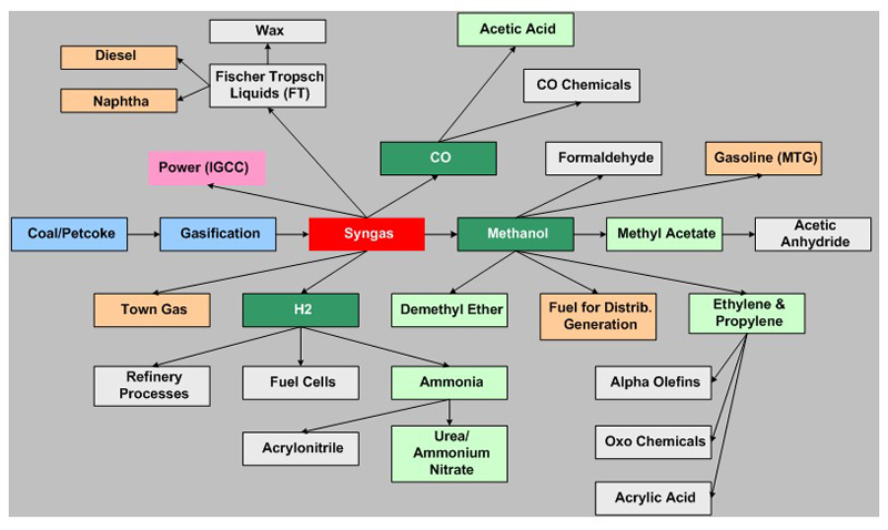
The processes for production of specific chemicals from gasification-derived syngas are typically proprietary systems using specialized process systems. In the following discussion, some of the processes for important chemicals such as formaldehyde, olefins, etc. are presented. Methanol (MeOH) is of course another important primary chemical made from syngas; however, it is also a liquid fuel in its own right particularly in certain markets (China). See detailed discussion of methanol synthesis and use under discussion of liquid fuels on the main portal in Gasifipedia.
Carbon Monoxide
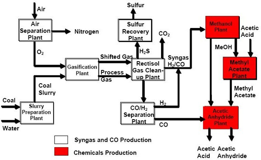
Referring to Figure 1, syntheses of certain chemicals require high purity carbon monoxide (CO) as a feedstock. This is obtained by separation from syngas, which can be accomplished by several commercial processes: cryogenic purification, pressure swing adsorption, membrane separation, and salt solution absorption. Cryogenic purification is normally the preferred process except when the syngas feed contains large amount of nitrogen (N2), due to the close proximity between CO and N2 boiling points (approximately 8°F). Under this situation, copper salt-solution absorption can be used instead. The Eastman coal-to-chemicals plant at Kingsport uses cryogenic purification for CO/hydrogen (H2) separation.
Figure 1: Gasification/Syngas Chemical Routes
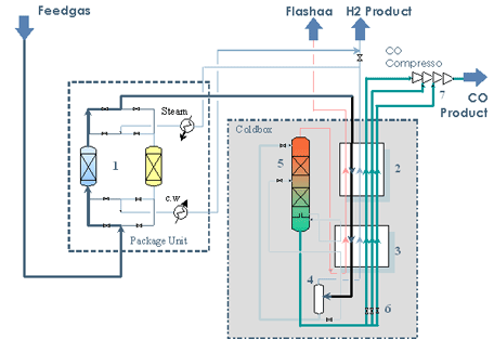
In the cryogenic CO/H2 purification scheme, syngas feed is first pre-treated with molecular sieves to remove carbon dioxide (CO2) and water before being chilled to approximately -300°F in a cold box by heat exchange against exit gases. Refrigeration is supplied by the cold product streams and by flashing the final CO liquid product stream exiting the stripping tower. Separation of CO/H2 and purge gas is accomplished by a series of condensation/depressurization steps, of which, depending on the operating pressure cycle, the overall heat exchange/recovery and refrigeration streams may vary and can become very complex. Figure 2 shows a simple configuration of this type of cryogenic CO/H2 purification process, including a molecular sieve adsorber station, and a cold box containing the plate fin heat exchangers to pre-cool the feed syngas against the product streams.
Figure 2: A Simplified Cryogenic CO/H₂ Purification Scheme
Acetic Acid and Derivatives
Acetic acid (CH3COOH), an important industrial chemical, can be produced from syngas-derived MeOH indirectly through carbonylation of MeOH over rhodium or iridium catalysts (with various iodide or other additives) according to the following reaction:
CH3OH
+
CO
→
CH3COOH
The rhodium catalyzed process is highly selective (>98% acetic acid) and operates under mild reaction pressure (~ 500 psia) in a liquid phase reactor. Technology licensors include Monsanto/BP, Celanese, BP, and Chiyoda, the latter three vendors represent an improved version of the original Monsanto/BP technology.
Figure 3 shows a simplified block flow diagram (BFD) of the Eastman Chemicals' coal-to-chemicals facility producing MeOH from coal derived syngas, followed by converting MeOH into acetic acid and its derivatives of methyl acetate and acetic anhydride.
Figure 3: Eastman Coal to Acetic Acid & Derivative Chemical BFD
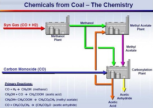
With the Eastman facility, acetic acid is reacted with MeOH to form methyl acetate (CH3COOCH3), which is further reacted with CO to produce acetic anhydride ([CH3CO]2O). The catalytic reactions for these additional derivatives are shown in Figure 4.
Figure 4: Eastman Coal to Acetic Acid & Derivative Chemistry
Formaldehyde
Formaldehyde can be produced from syngas indirectly through dehydrogenation and partial oxidation of MeOH using a silver catalyst, based on the following reactions:
CH3OH
→
HCHO
+
H2
∆H =
+ 36,700 Btu/lbmole
CH3OH + ½ O2
→
HCHO
+
H2O
∆H =
- 67,300 Btu/lbmole
Equilibrium conversion and potential side reactions are highly temperature dependent. The overall reaction temperature is controlled by the quantity of air (oxygen) used, and the addition of inerts, such as water and/or nitrogen.
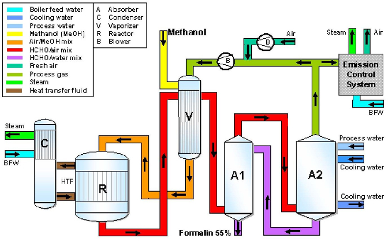
Figure 5 shows a typical flow scheme of a MeOH oxidative dehydrogenation process producing commercial grade formaldehyde. A mixture of methanol and water is mixed with air and recycled gas, and the total feed mixture is vaporized by heat exchange against hot reactor effluent. The vaporized feed mixture is fed into the catalytic reactor to form formaldehyde. Excess reaction heat is removed by generating steam. The reactor effluent, after cooled by heat exchanging with incoming feed, is scrubbed with water in the absorber to remove the formaldehyde product as a 55% solution. Water can be added to produce commercial grade formaldehyde at 37% concentration. A portion of the product gas leaving the top of the absorber is recycled, and the remainder is incinerated. Typical overall formaldehyde yield is in the range of 92 to 95%.
Figure 5: A Typical Methanol Oxidative Dehydrogenation Process of Producing Commercial Grade Formaldehyde
Olefins
Olefins, such as ethylene and propylene, can be produced from gasification indirectly by catalytic cracking of MeOH, commonly called the methanol-to-olefins (MTO) process.
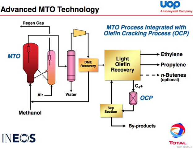
Figure 6 shows a simplified flow diagram of UOP’s MTO process. Other technology licensers include ExxonMobil and Lurgi, using different types of catalyst systems and process know-how. Per Figure 6, fresh MeOH feed is combined with recycled water and fed to a fluidized-bed catalytic reactor, equipped with a catalyst regeneration and recycle reactor as shown. The reactor operates at typically 350°C and at 30 psig. With UOP/HYDRO’s proprietary catalyst system, claimed methanol conversion is quite high, and the process is 80% selective for ethylene and propylene. The produced ethylene/propylene ratio can be altered from 1.5 to 0.6, depending on operation conditions.
Reactor effluent leaving the reactor is cooled to condense most of the water and unreacted methanol for recycling. Spent catalysts from the reactor are routed to the regenerator where the coke deposits are burned off with air. Regenerated catalysts are recycled. The cooled reactor effluent is compressed to remove CO2 and water, followed by further compression to high pressure to liquefy the hydrocarbon mixture for separation by distillation. The final product from distillation separation typically consists of polymer grade ethylene and propylene, a methane-rich fuel gas, plus small amount of ethane, propane, butane, pentane and higher molecular weight liquids. In the depicted flow diagram, the Total/UOP Olefin Cracking Process (OCP) is included to recycle heavier fractions to increase light olefins yield and feedstock efficiency.
Other MTO technology licensors include Exxon/Mobil and Lurgi, of which the ExxonMobil process is very similar to that of UOP/HYDRO except perhaps with the use of a different catalyst formulation. Lurgi's process is optimized for propylene production, and is being marketed as a methanol to propylene (MTP®) process.
Figure 6: UOP MTO Process Integrated with Olefin Cracking1