Business

Business
The project will design, build, and test a high-pressure linear-motor-driven leak recovery compressor for the cost-effective recovery of methane leaks within the transmission, storage, gathering, and processing sectors of the natural gas value chain.
Gas Technology Institute (GTI); Des Plaines, Illinois
University of Texas Center for Electromechanics; Austin, Texas
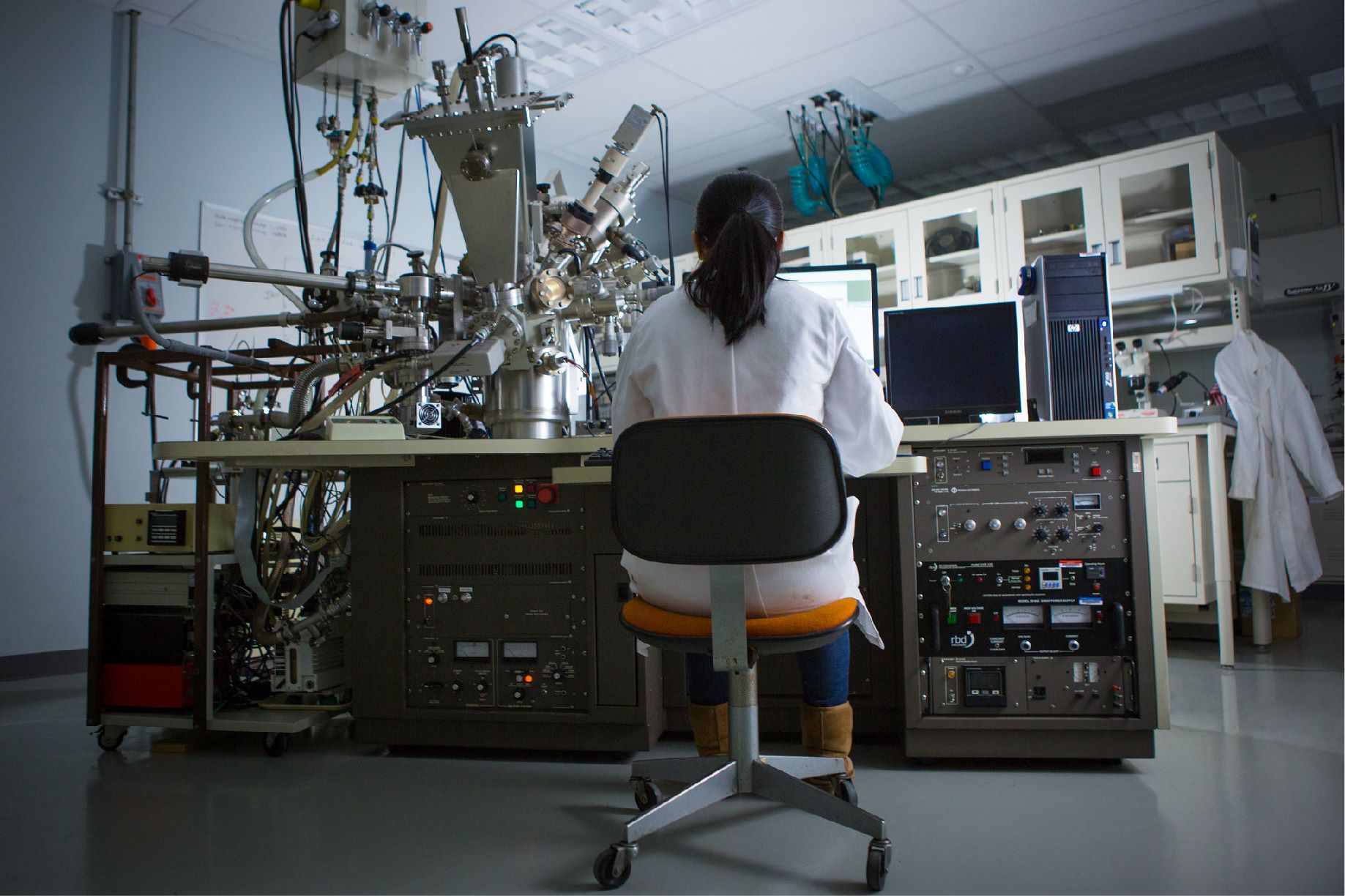
Large reciprocating and centrifugal compressors are central to the natural gas value chain. Across the U.S., around 8,000 compressors move gas through over 250,000 miles of large transmission lines and store it underground in high-pressure geological formations for use during high demand periods. These compressors are concentrated at about 2,000 compressor stations where they are maintained and operated year-round. These compressor stations also contain pneumatic controllers, storage tanks, and purge systems that are required to operate the compressors or direct flow in and out of the station.
These compressor stations represent potential methane emission sources, and though relatively small, they contribute a disproportionately large percentage (about 20%) of the total methane emissions from the entire value chain. The primary challenge preventing the capture and mitigation of these leaks is not a lack of will or desire, but rather the absence of a suitably engineered and priced solution.
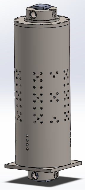
The project team will design, build, and test a fully functional linear-motor-driven leak recovery compressor and package it onto a full leak recovery system designed specifically to gather and recompress methane emissions from midstream transmission and storage compressor stations. The linear motor leak recovery compressor is uniquely suited to provide variable flow capabilities to match the variable leak rates inherent to this application. It is being designed for a high-pressure discharge to compress the gas back to midstream operating pressures, often over 1,000 psig. The team’s goal is to develop a unit that is less expensive than current compressors while still capable of reaching a discharge pressure of 1500 psig or more.
The simulation work is complete. The simulation shows that the compressor should be able to match real time leak rates from the compressor station vent gas piping and compress that gas back to 1500 psi for recovery in the pipeline. The compressor is being controlled using the vent gas pressure. As the pressure rises the compressor speeds up to maintain the vent gas pressure near the desired target, and as the flow and pressure drop the compressor will rapidly slow down to match those changes.
The large motor components have been delivered to GTI. The detailed design and drawings for the compressor components were finalized and reviewed. Bids were recently sent out to vendors that have been used in the past. The P&ID is also complete and GTI has been ordering the balance of plant components such as valves, filters, intercoolers, etc. for the full-scale leak recovery skid. The intercoolers were recently delivered to GTI and put in storage for assembly of the full unit. GTI is also preparing a test cell for the compressor including cleaning/painting, installation of lighting, starting installation of power and heat.
Assembly and preliminary testing of the leak recovery skid is anticipated in Q1 2023.
$1,499,918
$375,002
NETL – Kyle Clark (kyle.clark@netl.doe.gov or 304-244-9178)
GTI Energy – Jason Stair (jstair@gti.energy or 224-235-3579)