Back to Top
Skip to main content
NETL Logo
High-Temperature Logging While Drilling Tool
Project Number
DE-AC26-97FT34175
Goal

The goal is to improve the efficiency of drilling deep, high-temperature, directional and horizontal wells, by accelerating the development of measurement-while-drilling/logging-while-drilling systems capable of reliable operation at high temperatures. The tool was to utilize current off-the-shelf electronic technology and designs to achieve reliable service at 175° C with greater than 100 hours mean time between failures.

Figure 1 (above) - Pulser, Generator, Telemetry, Gamma (GM), and Directional (DM) modules in a drill collar. The modules are along the central axis of the drill collar. The pulser/generator section on the left in the drawing is installed at the top of the string. Drilling mud flows in the annular volume between the drill collar and the modules, from left to right in the drawing. The pulser is the left most element of the package (top of the downhole string) so that pressure pulses are not attenuated by other modules within the drill string bore. The GM module shown was removed from this section and installed in the gamma ray detection section of the EWR Slim Phase 4 tool (Figure 3 below).


Performer(s)

Sperry-Sun Drilling Services – project management

Location:
Houston, TX 77072

Background

As the market drives interest in deeper and hotter wells, logging-while-drilling (LWD) becomes more attractive technically and economically. Hotter holes are more expensive to drill and bring increased safety and economic risks as well. Borehole stability can be problematic, with higher temperature wells, increasing the risk of being unable to log the well with wireline tools or even losing the well entirely. LWD in unstable situations provides much better assurance than with a formation log that is obtained. LWD sensors measuring drilling-related parameters, such as downhole pressure and borehole diameter, can provide information critical to the successful drilling of the well in a hostile environment.

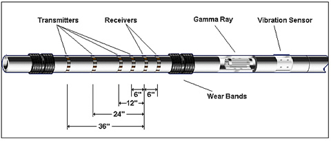
Oil well logging is the process of acquiring data for formation evaluation (FE), the purpose of which is to determine the location of hydrocarbons in the formation, as well as to estimate the quantity in place. The primary measurements on which FE relies are the natural gamma ray, resistivity, neutron porosity, and bulk density. The gamma ray and resistivity measurements assist in locating formations which are likely to contain hydrocarbons, and the neutron and density measurements are used to discriminate between oil and gas, as well as to determine the volume of hydrocarbons in the formation.

For most of well logging history, logs were obtained after the well was drilled. Tools were lowered into the well, and the measurements were obtained as the tools were pulled from the hole by a wireline, which provided both the power and the telemetry for the tools. During the 1980s and 1990s, tools for making these measurements were designed into drill collars. Sperry-Sun Drilling Services was a pioneering company in this field, introducing the first LWD neutron and density measurement tools, as well as the first electromagnetic wave resistivity (EWR) tool. The electromagnetic wave technology evolved to become the most popular type of LWD resistivity measurement in the industry.

While one goal of LWD is to replace wireline measurements, it also has become an essential technology in other areas, providing measurements which enable precision horizontal drilling and real-time information that can significantly enhance drilling efficiency and well safety.

LWD FE sensors, along with telemetry modules for communicating data to the surface in real time, are built into drill collars of various sizes to allow LWD throughout a well. Until recently, most LWD tools had a maximum operating temperature of around 150°C. This provided LWD capability in most interested reservoirs of the world. However, deeper wells where gas is frequently found can exceed this temperature.

To increase its presence in the high temperature (HT) market, Sperry-Sun developed the Solar 175 tool in the 1990s. This is a HT version of a Sperry-Sun system for economically making real-time directional and gamma ray measurements. Since borehole diameters in the deeper, higher temperature wells tend to be smaller, the Solar 175 tool was constructed in the smaller 4¾” diameter drill collar. This system provided the starting point for the HT-LWD system of this project.

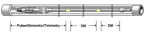
This “High Temperature LWD Project” was awarded by the U.S. Department of Energy in September 1997 with Sperry Sun. After this project began, Dresser Industries, the parent company of Sperry Sun, merged with Halliburton Company. Previous to the merger, Halliburton also had a sub-contract under Maurer Engineering. Maurer was contracted with DOE to build a HT, real-time directional/gamma system, consisting of modules for communication, power, directional, and natural gamma ray measurements. The technology and development departments of Halliburton and Sperry Sun were integrated, and the Maurer/Halliburton DOE contract was completed, resulting in a system qualified to operate at 195°C. The knowledge gained in the Halliburton DOE contract contributed to the HT-LWD project.

Impact

HT LWD tools will enable drilling of deeper, hotter formations. Areas in the United States where there are HT prospects include the western Gulf of Mexico, South Texas, Louisiana, and Mobile Bay. In the proposal for this work, Sperry Sun estimated the total US market for wells above 150°C to be about 900 per year, with about 60 of those being offshore in the Gulf of Mexico. Although an update to those estimates was not undertaken as part of this project, there almost certainly has been less activity on land than was anticipated earlier. However, the volume of Sperry Sun's HT work in the Gulf of Mexico appears to have remained consistent with that estimation.

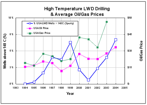
An internal survey of the HT work of Sperry Sun suggests a growing significant impact to the industry. The survey shows the fraction of Sperry Sun's work over the last decade that took place in wells with a measured temperature exceeding 140°C. It is assumed that the formation temperature is, on the average, 10°C higher than the temperature measured by the tool. A measured downhole temperature of 140°C corresponds, then, to a formation temperature of 150°C, along with corresponding annual average prices for oil and gas. The fraction of Sperry Sun's market falling within the “high temperature” category shows a robust growth rate of ~1% per year in the periods 1995 to1999 and 2001 to 2004. Higher cost, HT drilling activity should be especially sensitive to adverse economic conditions such as a recession. If we interpret the dip in HT work in 2001 as a consequence of the contemporaneous economic slowdown, a reasonable conclusion from the data suggests an industry growth for drilling in HT situations.

Although a working HT-LWD system has been demonstrated at 175°C, HT operation will probably be needed in order to address deeper, hotter, harsher gas resources and the geothermal market.

Accomplishments (most recent listed first)

This project includes two phases. The first was to design, construct, and test 2 prototypes in a laboratory environment with potential for a limited field test. The second phase involved testing of the prototype(s) in an actual well with a bottom hole temperature suitable to demonstrate reliable extended performance at 175° C.

  • Pulser and telemetry systems were upgraded to HT specifications and successfully tested in the lab and field.
  • A 4-3/4 inch diameter Solar (175ºC) stabilized litho density (SLD) measurement tool was built and rigorously tested at Halliburton's North Belt manufacturing facility.·
  • Tool infrastructure/data management modules were developed and tested to 175/200°C. FE sensors for gamma ray (DGR), resistivity (EWR), neutron (CTN), and density (SLD) logging were developed and lab tested to 175°C and 200°C survival, and then field tested.
  • Field testing was accomplished on five of the tool components in the North Sea at depths in excess of 15,000 feet and temperatures up to 186ºC with excellent success. Field tests were also conducted in Oman (174ºC), Saudi Arabia (162ºC), and the Gulf of Mexico (154ºC).
  • Component and module field testing has indicated that system life goals will be substantially exceeded. System data from the field are consistent with this but are as yet too limited to provide a firm validation.
  • HES is commercially marketing this tool around the world.
Current Status

and Remaining Tasks: 
The project has been completed and the LWD technology is now being applied commercially.

Project Start
Project End
DOE Contribution

$1,283,008

Performer Contribution

$320,752

Contact Information

NETL – John D. Rogers (john.rogers@netl.doe.gov or 304-285-4880)
Sperry-Sun – Bill Motion (bmotion@halliburton.com or 281-871-4412)

Additional Information

Images:

Figure 2 (above) - HES LWD potential only
Figure 3 (above) - Resistivity/Gamma Tool. The EWR Slim Phase 4 is actually several tools in one drill collar. Four different resistivity readings, sensitive to various radial depths away from the borehole, are produced by waves emitted by the four differently spaced transmitters. The phase difference for each transmitter is measured at the receiver pair. The electronics inserts (not indicated in the figure) controlling the transmitters and receivers are located inside the bore of the drill collar immediately to the left and right, respectively, of the transmitter and receiver antennas. The antennas themselves are wire loops, installed in grooves around the tool and covered by the circumferential bands indicated in the drawing. The gamma ray detectors, indicated in the “cutout”, are located on the receiver insert. A vibration sensor provides information about average g levels and maximum shocks experienced by the tool. The wear bands are carbide rings around the tool that abrade over time as a result of contact with the formation. They significantly extend the life of the tool and drill collar.
Figure 4 (above) - Compensated Thermal Neutron (CTN) Tool. The neutron source is installed in the source port just prior to the tool going downhole. Neutrons with MeV energies emitted from the AmBe source slow to thermal energies as a result of collisions with atomic nuclei in the formation and borehole. The slow, thermal neutrons are detected by He3 Near and Far detectors which are mounted on an insert which is installed from the “box” end of the drill collar (right in the figure). Events from the detectors are recorded by electronics which are also located on the same insert. Because the hydrogen located in the rock pore space is the most efficient element in slowing neutrons, the formation porosity can be inferred from the thermal neutron detection rate.
Figure 5 (above) - Stabilized Litho Density (SLD). The density is determined from the scattering of gamma rays emitted by a cesium source installed in the source port. The detectors are mounted in a pressure housing that is installed in periphery of the drill collar, while the remainder of the electronics are on an insert installed in the box (right). Tungsten shields between the source and detectors — and between the detectors and the inner bore of the tool — minimize the number of gamma rays entering the detectors by paths other than through the formation. The stabilizer reduces alternative path of gamma rays through the borehole rather than through the formation. The acoustic sensor provides a measurement of the distance of the tool from the borehole wall, a measurement useful in quality control. Azimuthal sensors are located on the insert.