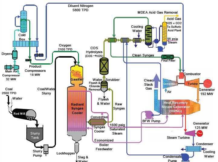
Figure 1 depicts the overall process configuration of a notable IGCC power generation unit located in the United States, the TECO Polk Power Plant Unit 1. This unit is quite representative of IGCC plants in general; further information is provided on the dedicated page for the Tampa Electric IGCC project.
Figure 1: Tampa Electric IGCC Process Flow
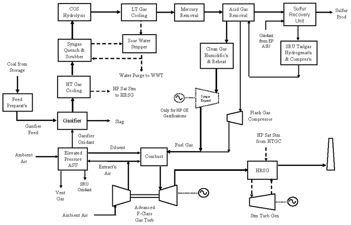
Figure 2 shows a simplified block flow diagram (BFD) illustrating the major process sub-systems included in a typical IGCC plant. The BFD shows an elevated-pressure (EP) air separation unit (ASU) integrated to the gas turbine (GT) operation by extracting some of the GT air compressor discharge as feed to reduce the ASU air compressor size and power consumption. Many IGCC plants including Polk Power Unit 1 have EP ASU integration with the GT as depicted in both Figures 1 and 2. Oxygen-depleted nitrogen from the EP ASU is compressed back to the GT as diluents for nitrogen oxide (NOx) control, and to maintain mass flow through the GT.
Figure 2 : IGCC Block Flow Diagram
A more detailed process description of each of the processing units within an IGCC complex is presented in the discussion on IGCC process system sections.
Effect of CO2 Capture
The flow scheme of Figure 2 represents a typical process arrangement of a near-term commercial IGCC design without CO2 capture. CO2 capture and sequestration (CCS) significantly impacts the overall IGCC efficiency, and the effects are addressed in the discussion Pre-Combustion CO2 Capture for Gasification Application.
NETL’s Support in Advancement of IGCC Technology
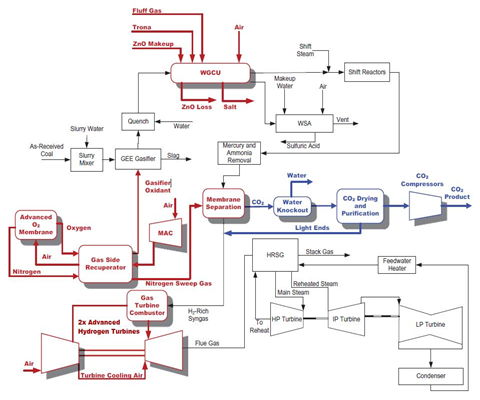
DOE’s R&D program has helped develop multiple technologies to improve and increase efficiency of conventional IGCC technology discussed above. Cumulatively, the technology advances targeted both more efficient production of electric power with significant reduction in the cost of electricity (COE). An IGCC cycle including carbon capture that incorporates these advanced technologies is depicted in Figure 3. The impact of each technology on both process performance and cost were evaluated, and by way of summary the following technological advances and their benefits are expected1:
Advanced hydrogen turbine (AHT): The AHT replaces the state-of-the-art F-class turbine (F-class is currently used at Tampa, Wabash River, and is depicted in the baseline IGCC in Figure 2). Its higher firing temperature (~2650°F) both improves the process efficiency and results in ~45% increase in gas turbine output, mandating increased flow rates such as coal input and significantly boosting power capacity. Plant units are larger to accommodate the increases, resulting in economies of scale which deliver unit capital cost reductions. Quantitatively, upgrading the turbine decreases COE 14.5% and increases process efficiency by 3 percentage points.
Ion transport membrane (ITM) for oxygen production: The ITM-based oxygen unit replaces the conventionally used cryogenic ASU. The ITM provides more energy efficient separation than the ASU, but the auxiliary duty for compression of the inlet air and low-pressure oxygen results in net power consumption similar to the ASU. The significant advantage of the ITM is that the targeted cost is approximately two-thirds of the ASU, which significantly reduces the capital costs and results in a 3% reduction in COE. Configurations including air-side integration with the turbine are anticipated to further increase the efficiency and COE benefits of the ITM.
Warm gas clean up (WGCU): This system replaces the desulfurization Selexol stage, mercury removal process, water-gas shift reactor and Claus plant, performing all of these operations at elevated temperatures which allows for the syngas to be cleaned without the associated decrease in efficiency from cooling and reheating the fuel gas stream. Implementing the WGCU process train results in a 2 percentage point increase in net plant efficiency, which is mostly the result of increased power generation from the steam turbine via increased heat recovery from the process. A 4% decrease in COE is also realized.
Hydrogen membrane for pre-combustion capture: Palladium-based 100% hydrogen-selective membrane replaces the Selexol stage for CO2 capture from the syngas. Use of the palladium membrane improves plant efficiency by 1.4 percentage points mostly from the lower compression costs of CO2. The COE is further reduced by 3%, again mostly due to lower compression costs.
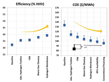
Successful implementation and integration of all these advanced technologies allows for an estimated increase of 7.0 percentage points in efficiency, as shown in Figure 4. Coupled with increased availability and improved financing structure, a reduction of 28% in COE relative to the state-of-the-art carbon capture IGCC plant has also been estimated.
Figure 4. Cumulative Impact of advanced IGCC technology on net plant efficiency and COE¹
References/Further Reading
"Current and future power generation technologies: pathways to reducing the cost of carbon capture for coal-fueled power plants” Kristin Gerdes, Robert Stevens, Timothy Fout, James Fisher, Gregory Hackett, Walter Shelton, Energy Procedia 63 (2014) 7541 – 7557.